Categories
Important Links
- Meian Technology
- Hengbo security technology
- HST fire alarm system manufacturer
- Home Security and Smart Home
- Dropshipping
- Security service alarm video server
- How to Choose an Infrared Beam Detector
- New equipment for outdoor security
- How to debug infrared beam alarm
- Infrared Beam VS. Microwave Beam Detection
- UV flame detector
- Wireless Community Alarm System
Fire Alarm Linkage Fire Fighting
TC5109 Intelligent Fire Alarm And Linkage Fire Fighting Security Control Panel
Core Functions
1. Fire Alarm Monitoring
Detect fire signals from addressable smoke/heat detectors, manual call points, and other fire-sensing devices.
Display the first/last fire alarm, zone location, device address, and time stamp in real time.
Trigger fire alarm output (HJ+/HJ–) and sounder strobe for on-site audible-visual alert.
Fault Detection & Indication
Monitor system faults: main power fault, battery fault, loop communication fault, system fault.
Monitor field device faults: detector fault, module fault, sounder strobe fault, FPE fault, zone fault.
Output fault relay signal and show fault information on LCD and LED indicators.
2. Device & Zone Management
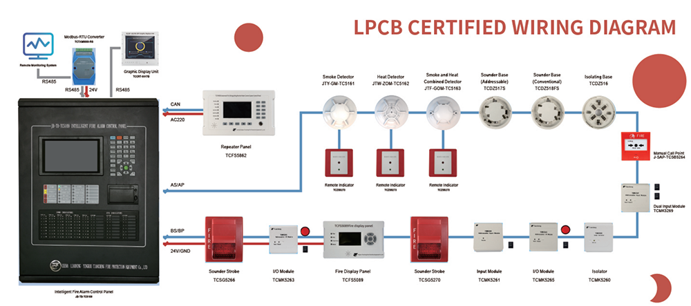
Support up to 4 loops, max 255 addressable points per loop, total 1020 points.
Support up to 48 zones with independent fire alarm and fault/disable indicators.
Support device registration, query, definition (second code, type, attribute, location note).
Support zone/addressable point/sounder/FPE disable and enable.
Linkage Control
Automatically start/stop FPE devices (I/O modules, fire dampers, fire pumps, etc.) via logic linkage formulas.
Support linkage action and feedback signal display.
Support offline programming via USB for linkage logic and device notes.
3. Installation & Maintenance
Modular plug-in structure for easy installation, commissioning, and expansion. Loop short-circuit isolation via loop isolator to ensure system stability.
Regular test guidance and common fault troubleshooting.
3.1 Install the components(detectors models isolators and so on)
The loop terminals on the control panel are L1 & L2 which are non polarity. (For TC5109 Control Panel, the loop terminals are from BS1 (OUT) to AS1 (IN); BP1 (OUT) to AP1 (IN) )
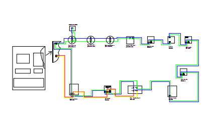
There are some components need to connect to 24V and GND terminals such as sounder strobes & I/O models.
The wire should be RVS wire, sectional area > 1mm^2 .
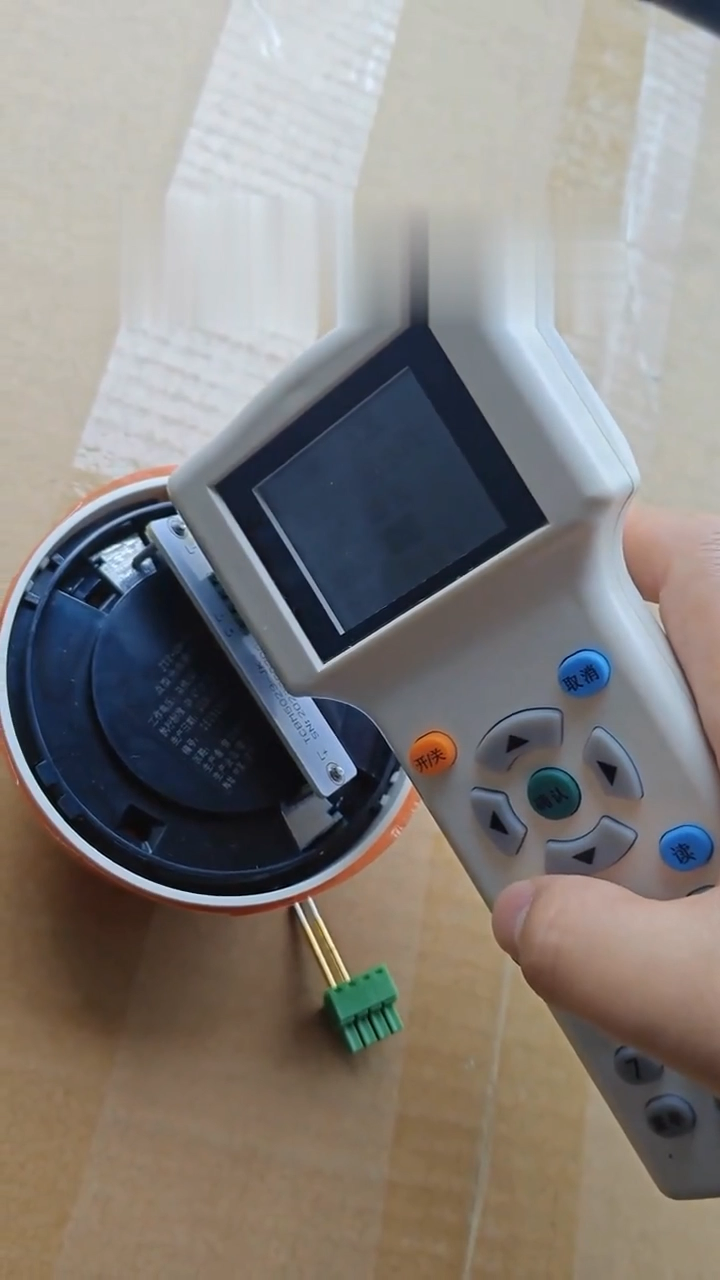
3.2 Encoding addresses for components
Encode each component with an address which can not be repeated by using the Handheld Encoder TC5023.
3.3 Register the devices
Control panel:
Press “Menu” ---Press “5 system setup”---Press “1 Device registration” and press “Enter”to start System registration.
The system will reset automatically after registration completed.
3.4 Linkage programming
offline linkage program
(Using programming software to make linkage program and download to the control panel)
When heat detectors or MCPs set fire signal ,the sounder strobes will alarm though the linkage program.
Linkage programming manually
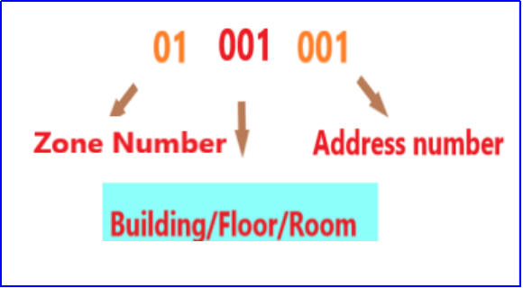
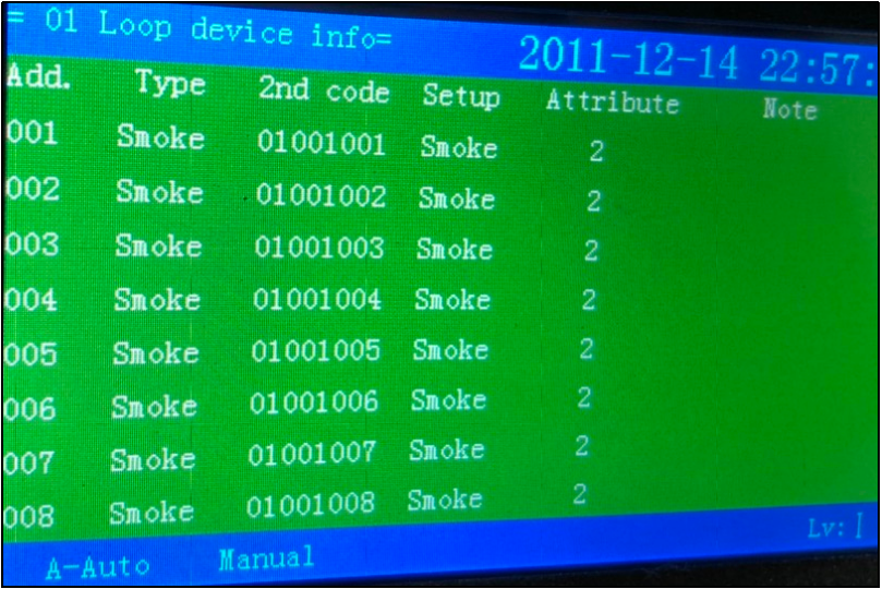
Program 2nd code for each component
Manu---Press 5 System Setup---Press 3 Loop component setup
Write linkage program manually
Menu----Press 7 Linkage Program---Press 1 common linkage program
3.5 System test
When all above are completed, no faults display, start system test.
3.6 Networking Mode
When there are two sets or more control panels, them can be connected together to be a network. One or some could be master mode, some to be slave mode. Each control panel should arrange an individual address, the address number should not be repeated.