Categories
Important Links
- Meian Technology
- Hengbo security technology
- HST fire alarm system manufacturer
- Home Security and Smart Home
- Dropshipping
- Security service alarm video server
- How to Choose an Infrared Beam Detector
- New equipment for outdoor security
- How to debug infrared beam alarm
- Infrared Beam VS. Microwave Beam Detection
- UV flame detector
- Wireless Community Alarm System
UV flame detector
I. CF6002 Point UV Flame Detector Overview
The CF6002 point-type ultraviolet flame detector detects fires by detecting the ultraviolet light produced by burning materials. It is suitable for locations where open flames are likely to occur during a fire, and can be used for fires with strong flame radiation, fires without a smoldering stage, and fires requiring a rapid response. When used in conjunction with other detectors, the CF6002 ultraviolet flame detector can detect fires more promptly and minimize losses.
II. Features of CF6002 Ultraviolet Flame Detector
The CF6002 detector features a built-in microcontroller and intelligent algorithms, enabling rapid alarm response while minimizing false alarm rates. It employs a relay-type output (normally open or normally closed selectable) for direct control of other devices. The sensor utilizes a high-performance imported ultraviolet phototube, offering advantages such as high sensitivity, reliable performance, and strong resistance to dust contamination, moisture, and corrosion.
III. Technical Characteristics of CF6002 Point-Type Ultraviolet Flame Detector
Operating voltage
Rated operating voltage: DC24V;
Operating voltage range: DC12V~DC30V
Operating current
Monitoring current: ≤10mA;
Alarm current: ≤30mA
Output capacity
Passive normally open or normally closed output (selectable via JP1 on the detector's internal PCB, either normally open-NO or normally closed-NC), contact capacity 1A, DC24V.
Output control method
The detector can be set to either lock or unlock via jumper (JP2) on its internal PCB board.
Alarm self-locking method
After the detector alarms, it locks into alarm mode and can only return to normal mode after power is cut off.
Alarm non-self-locking method
After the detector alarms, it can automatically return to normal operation once the fire alarm source is deactivated.
Power-on time ≤3S
indicator lights
Under normal conditions, it flashes approximately every 5 seconds to indicate monitoring status; it remains lit during an alarm.
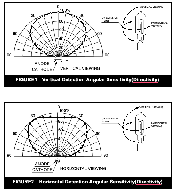
Spectral response range 180nm~290nm
Detection perspective As shown in Figures 1, 2, and 3
Detection range
Level 1 (25m). Test conditions (GB12791-2006): Flame produced by the combustion of 2000g of industrial ethanol in a container with a bottom area of 33cm × 33cm and a height of 5cm.
Wire
Nonpolar two-wire system
Usage Environment
Temperature: -20℃ to +55℃
Relative Humidity: ≤95%, non-condensing
External dimensions
Diameter: 103mm, Height: 45mm (with base)
Enclosure protection rating: IP21
Casing material and color: ABS, gray-white
weight: 153g
Mounting hole spacing: 45mm~75mm
IV. Technical Characteristics of JT-GB-ZW-CF6002 Ultraviolet Flame Detector
1. The detector's structural diagram is shown in Figure 4. The detector has a built-in microcontroller that performs signal acquisition and fire alarm judgment functions.
2. The detector is powered by a DC power supply, which, after voltage regulation, provides power to the signal processing circuit. The sensor uses a technologically advanced high-performance ultraviolet phototube, and the high voltage required by the sensor is provided by a transformer. When ultraviolet light of a specific wavelength shines on the ultraviolet phototube, the phototube discharges due to the photoelectric effect. The intensity of the discharge is proportional to the intensity of the incident light. The signal processing circuit shapes the output signal from the ultraviolet phototube, and the microcontroller samples the shaped pulse. If the sampled value meets the alarm conditions set by the algorithm embedded in the microcontroller, the detector will output an alarm signal.
V. Installation and Wiring of CF6002 Ultraviolet Flame Detector
Warning: Before installing the detector, disconnect the power supply to the circuit and ensure that all bases are securely installed and that the connection points of the wiring on each base are accurate. 1. Before installation, first check that the detector housing is intact and that all markings are complete. 2. The detector can be installed on an 86H50 type pre-embedded box. An installation diagram is shown in Figure 5.
Figure 6 shows a schematic diagram of the positioning base for the JT-GB-ZW-CF6002 ultraviolet flame detector. The detector's incoming wire is threaded through the inlet hole of the pre-embedded box and the inlet hole of the positioning base, and the positioning base is then fixed to the pre-embedded box.
Figure 6 Schematic diagram of the detector positioning base
3. The positioning base has four terminals with numerical labels: "1" and "2" are relay outputs, and "3" and "4" are power supplies; these are non-polarized. 4. The detector and positioning base have positioning bayonets, ensuring the detector has a unique installation position. The positioning base has two protruding ridges at points A and B, and the detector has one protruding ridge on its bottom side at point C. During assembly, align the detector's protruding ridge C with point A on the positioning base and rotate clockwise to point B to install the detector. 5. Wiring requirements: The relay output wire uses RVS type twisted-pair cable with a cross-sectional area ≥ 1.0 mm² ; the power supply wire uses BV wire with a cross-sectional area ≥ 1.5 mm² .
